CNC is Computer Numerical Control and works in various industries, including aerospace and medical care. A CNC milling machine is a device controlled by numerical computer control. The CNC milling process uses the CNC milling machine, which rotates its cylindrical cutter, moving along multiple axes and creating slots or holes. CNC machines generate more precision and functions on three to five-axis.
The milling process begins with the creation of a 2D or 3D CAD. The design should be in a CNC-compatible file format, so it’s then converted to a readable CNC format. The CAM software then converts the file into a CNC machine program, which will read the machine’s actions and the movement of the tools across the workpiece.
Once the milling process starts, the machine begins to rotate the cutting tool at a speed of thousands of RPM. It performs the following actions when the device starts to cut into the workpiece as per the application requirements.
It pushes the workpiece into the stationary rotating tool and moves the device across the workpiece.
It then pushes the tool and workpiece about each other. Once the milling process completes, the product goes to the post-processing stages.
The components of CNC milling machines
A CNC milling machine consists of the following components.
- Spindle
The spindle is the core of the milling machine. It has a rotating assembly and a tapered section that holds the tools holders. It has a shaft that attaches the tools from the tool holder. A motor with varying transmission levels rotates the spindle; a spindle can be vertically or horizontally positioned depending on the type of CNC milling machine.
- Frame
The frame is the structure that keeps the CNC milling machine firmly in position. It consists of a base, detachable columns, and a headstock where the spindle is mounted. The headstock has to be rigid enough to keep the spindle strong enough.
- Axes
A CNC milling machine consists of an X/Y/Z rotational axis or C/A/B, depending on the Configuration. These are programmed using G Code in the CNC controller.
- Columns
The columns can be single or double, depending on the machine’s complexity level.
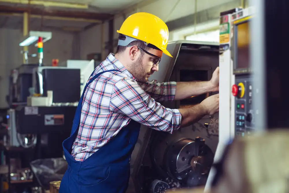
- Control panel
The CNC control panel comes with electronics that assist in controlling different cutting actions via programming functions. It is the nervous system of the machine and consists of a monitor and programming buttons for entering data and programming codes.
- Table
The table holds the vice and fixtures and provides a base for the workpiece. Tables may contain T-slots that help to clamp the vice or fixture easily.
- Automatic Tool Changer
Automatic tool changers usually come mounted on the columns or separately to the machine. Mounting separately to the device is preferred when there’s a need for more prominent tool changers that can hold 40- 300 tools.
- Tool holders
These hold the tools in place. They can be BT 30 to BT 50, with BT representing the taper angle of the cone. They come in varying sizes for different applications.
- Coolant Tank
A coolant tank will help cool the spindle or surface area while machining occurs. The cooling process helps to lengthen the machine’s lifespan and keep temperatures under control of the heat produced during milling.
Using G code
G code is a compact and concise language that makes use of blocks. G code is a programming language that controls CNC machines and is just instructions that control the device. The codes tell the machine what to do and where to go.
The following are some of the blocks.
G01 X1 Y1 F20 T01 M03 S500
G01 instructing the machine to perform a linear feed move
X1/Y1 move to X and Y coordinates
F20 move at a feed rate of 20
T01 make use of Tool 1
M03 switch on the spindle
S500, the spindle speed should be 500
So, these instructions will be many telling the machine what to do, and the device will be reading them from left to right.
You will find a G code program written in such a way that the machine will understand that it’s time to
- Start the CNC program by loading the required tool
- Turning the spindle on as well as the coolant.
- Move to a position above apart.
- Start the machining process.
- Turn off the coolant and the spindle
- Move away from the par to a safe place
- End the CNC program
Using M- code
M code is the language that Autocad and CAM use to input instructions into the CNC machine. It primarily tells the machine when to start and cease operations. The M code language is the one that tells any machine tool to run or turn off. M codes start from M00 to M99, continuing in an arithmetic progression. Below is a typical M code instruction set of how it controls the CNC machine.
M00 Program stop
M01 Optional program stop
M02 End of program
M03 Spindle start forward CW
M04 Spindle start backward CCW
M05 Spindle stop
M08 Coolant on
M09 Coolant off
M29 Rigid tap mode
M99 End of program
- Face milling
Face milling is a machining operation that allows you to put the milling cut perpendicular to the workpiece. It is essentially placed face down towards the top of the workpiece, and when it’s running, the top of the milling cut grinds away the top of the workpiece and removes some of its materials.
- Plain milling
Plain or surface milling is another machine operation that produces a flat, horizontal surface parallel to the cutter’s rotation axis. Secure the workpiece properly onto the machine and start the engine after selecting the correct speed and feed.
- Angular milling
Angular milling involves coming up with a workpiece that is angular in shape instead of right angles of the axis of the machine spindle. The production of V blocks is an example of angular milling.
- Form milling
Form milling makes use of form cutters to produce irregular contours. The cutting rate of form milling is usually 20-30 % less than that of plain milling. A template gauge verifies the formed shape, and the condition can be either concave or convex.
- Gear cutting
Gear cutting is a process that takes place in the milling machine using a form relieving cutter, which can be cylindrical or end mill type. Hold the workpiece on a universal dividing head, indexing it to cut equally spaced gear teeth on a gear blank.
- Straddle milling
Straddle milling involves producing a flat vehicle surface on either side of the workpiece, using two milling cutters mounted on the same arbor. Straddle milling is common in square and hexagonal surface designing.
- Profile milling
Profile milling involves reproducing an outline of a template or complex shape of a master dies on a workpiece. Profile milling uses different cutters, including end mills.
- Gang milling
Gang milling and machining time. It involves milling several surfaces of a workpiece simultaneously by feeding the milling table against several cutters with the same or different diameters placed on the machine’s arbor. That is why it is ideal for repetitive work.
Bed type mills
The bed-type mills are enormous, heavy, and rigidly constructed milling machines with a table directly mounted on the ways of a fixed bed. The table reciprocates at a right angle to the spindle axis, restricting its movement. It has no provision for cross or vertical adjustment.
It comes as simplex, duplex, and triplex with single, double, and triple spindle heads.
Knee type milling machines
Examples of knee-type milling machines are vertical, universal, hand milling machines, etc. These are generally ideal for shop work with the table mounted on the knee casting and further mounted on the vertical slides of the central column. You can adjust the column to suit various workpiece heights. Knee-type milling machines depend on different methods of supplying power to the table, the table movements, and the rotational axis of the spindle.
Planer type
Planer type, sometimes called Plano miller milling machine, is a large, heavy-duty machine used for massive work with a spindle head adjustable vertically or transversely.
The machine comes with a cross rail which can be raised or lowered when carrying the cutters. Because it drives multiple cutter spindles, it reduces the production time.
Ram type milling machines
Ram-type milling machines have all the features of the column and knee-type milling machines. Ram type has an additional movable ram with a vertical milling head mounted on the top of the column. The ram is mobile in the transverse direction with power.

- Grain and Sheen: Teak Oil versus Danish Oil Uncovered - January 10, 2024
- The Cherry on Top: Crafting the Perfect Cutting Board - January 9, 2024
- Polyurethane Water-Based vs Oil-Based: Choosing the Right Finish - January 8, 2024